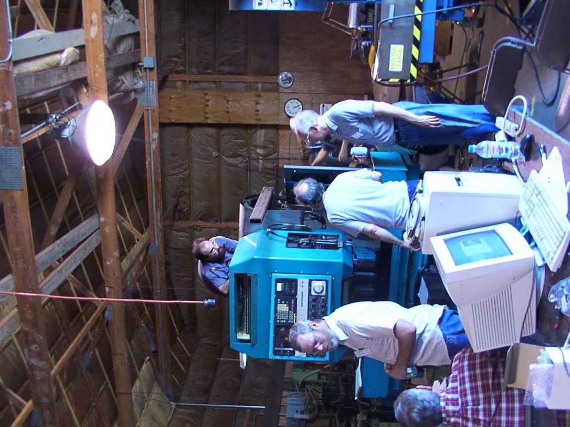
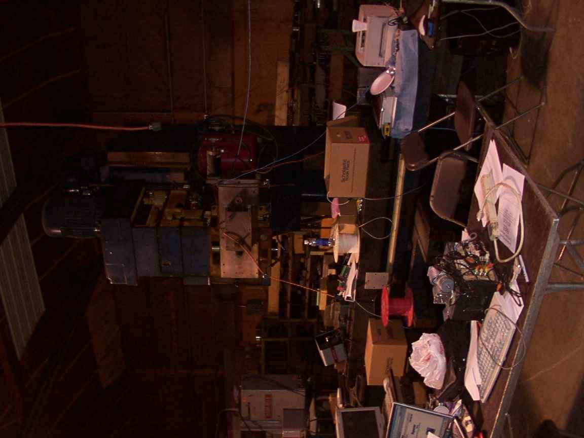
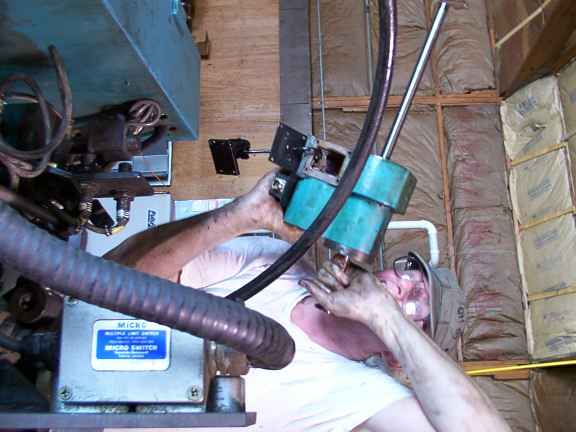
John Kasunich on top of the machine, Pete Gruendeman in light blue with his back turned, Dave Engvall on the right. Notice that the shroud and original panel are still installed. (sorry the picture is sideways)
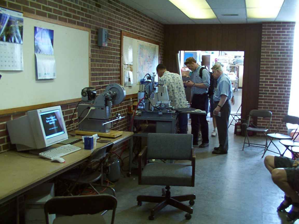
Held at the first annual CNC-workshop in Galesburg, IL, from June 19-27 2005. The goal of this project was to rip out the guts of a non-functioning Mazak Micro V machining center, and replace them with a modern PC running EMC and some simple I/O circuitry.
New! Some more pictures have surfaced here and here
IRC logs that may be of interest: #emc-mazak (steves_logging) and emcmazak (logger_aj)
Pitfalls: If we were to do it over again, we would simply remove all the signal wires and re-wire them the way they ought to be, instead of spending three days trying to figure out the naming system and buzzing out all the connections. Also, the servo amps require an analog velocity input signal, which is generated from the position encoder pulses on the old motherboard, which was ripped out. DOH! Solution? Get a new amp that can handle position feedback, or get/make a board that will convert position to analog velocity signals. Don't be afraid to spend a little money.
Warning: This is more than a one-week project. Make sure you have lots of documentation for the machine before you even think about doing anything. Test your Emergency-stop circuit BEFORE the machine decides to lash out at you. Ours failed because of a sticky power relay on the servo amp, but there could be more issues involved as well. The original factory setup foolishly ran all of the E-stop signals through the computer. Never trust software when your life is on the line. Always remember that murphy's law is in effect. The machine won't necessarily stay still if you tell it to, and in fact it began moving wildly as soon as we gave it some power, and then some. It might not be a bad idea to just disconnect the motor wires completely and use a motor you have lying around the shop for testing purposes.
Names listed from left to right. Captions underneath pictures.
John Kasunich on top of the machine, Pete Gruendeman in light blue with his back turned, Dave Engvall on the right. Notice that the shroud and original panel are still installed. (sorry the picture is sideways)
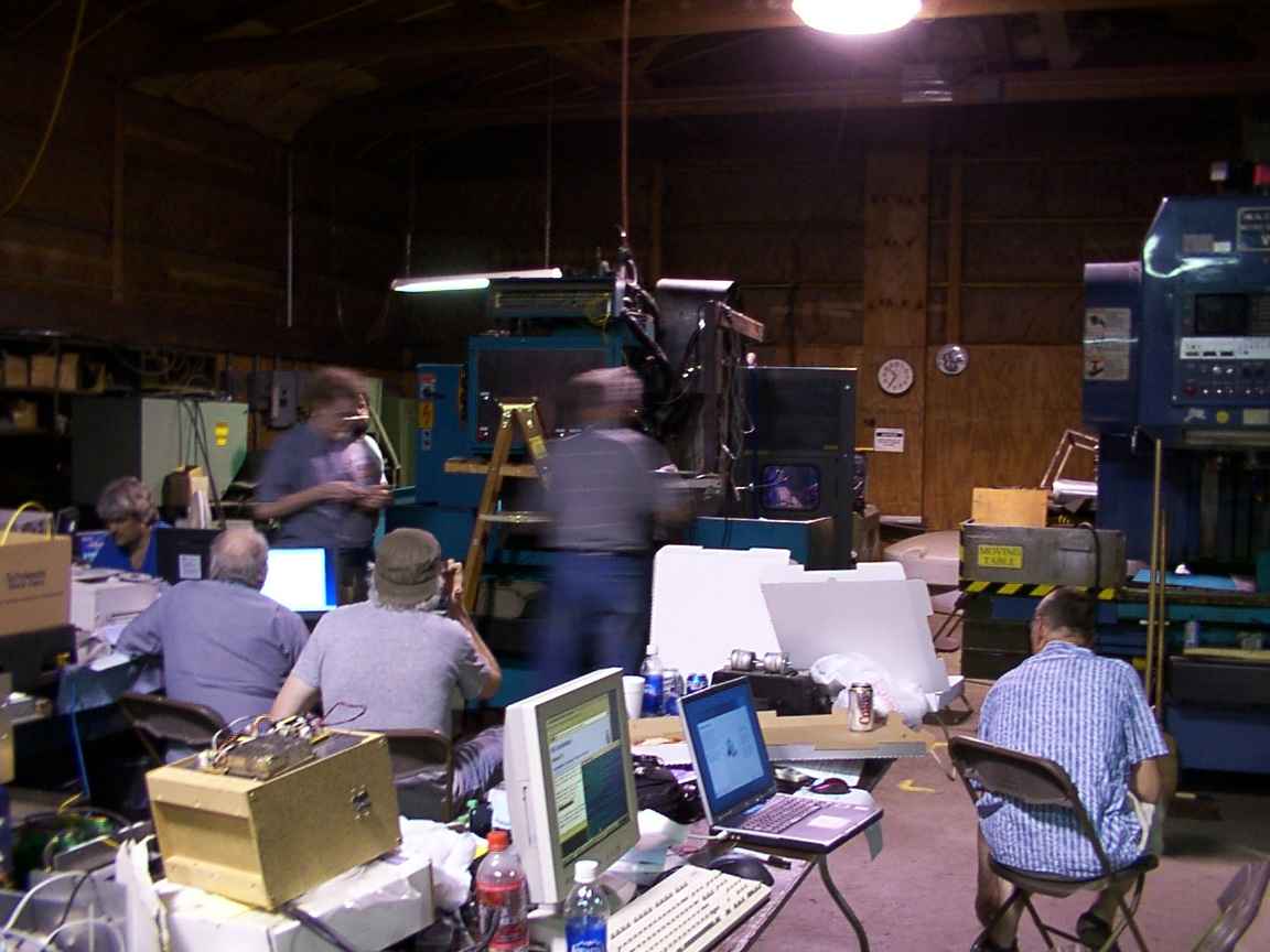
A blur of activity. Background: Matt Shaver, someone's wife, Dave Engvall? Foreground: Ray Henry, Tom Powderly, Rick Chownyk. The pegboard and 1x1 box is Dave's test servo power supply. It's 10:30 PM Wednesday June 23rd.
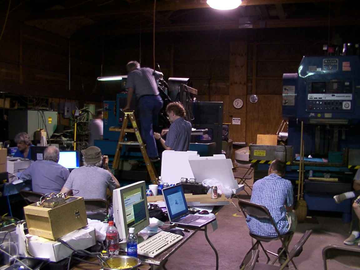
Background: Matt Shaver, Dave Engvall, Jon Elson. Foreground: Ray Henry, Tom Powderly, Rick Chownyk.

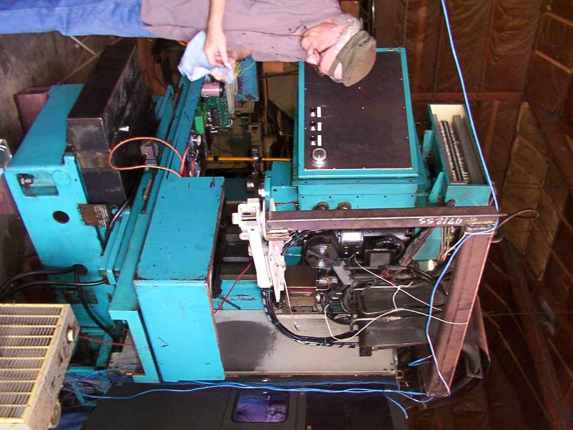
Tom Powderly, Dave Engvall, John Kasunich. The shroud has been removed, a new front panel installed, and a new rusty computer mount has been installed. Thursday morning, 9:00 AM. Most of the work up to this point was in re-routing wires to and from the front panel, and wiring in a new E-stop chain to replace the dangerous factory setup that ran all the E-stop signals through the computer motherboard.
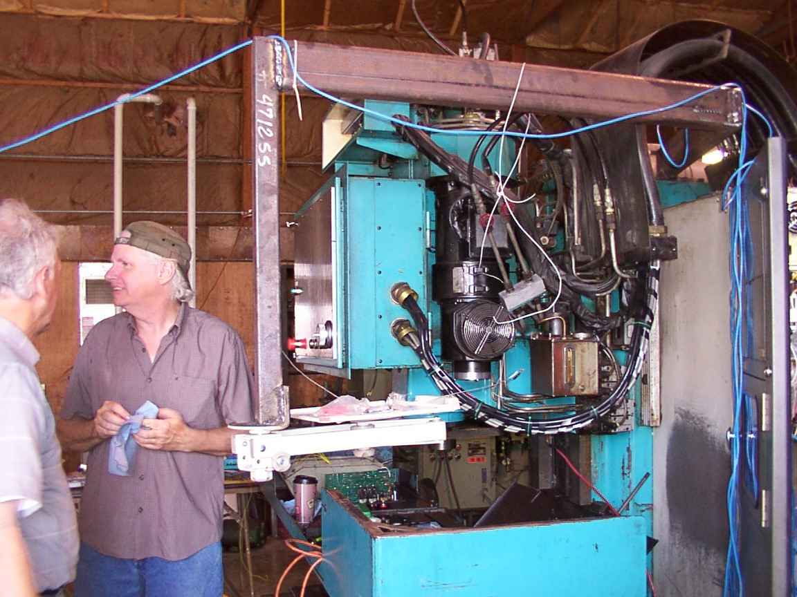
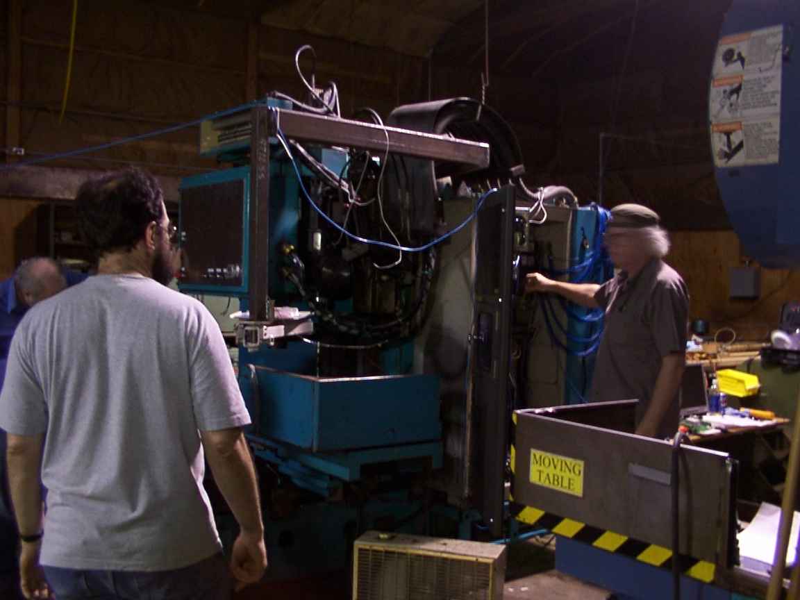
Dave, Tom, and the Mazak. The blue cable is an ethernet connection. The monitor and keyboard will eventually sit on the white tray/arm in the foreground.
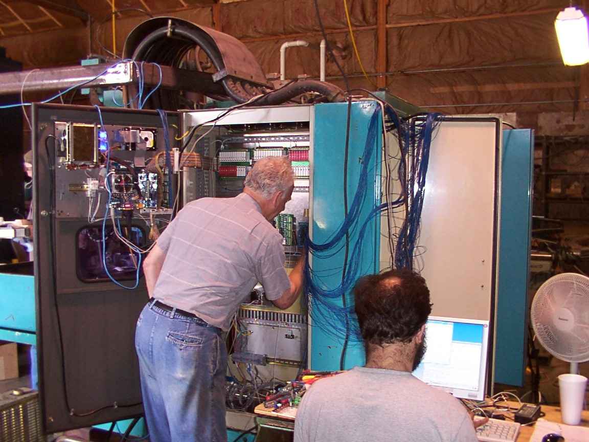
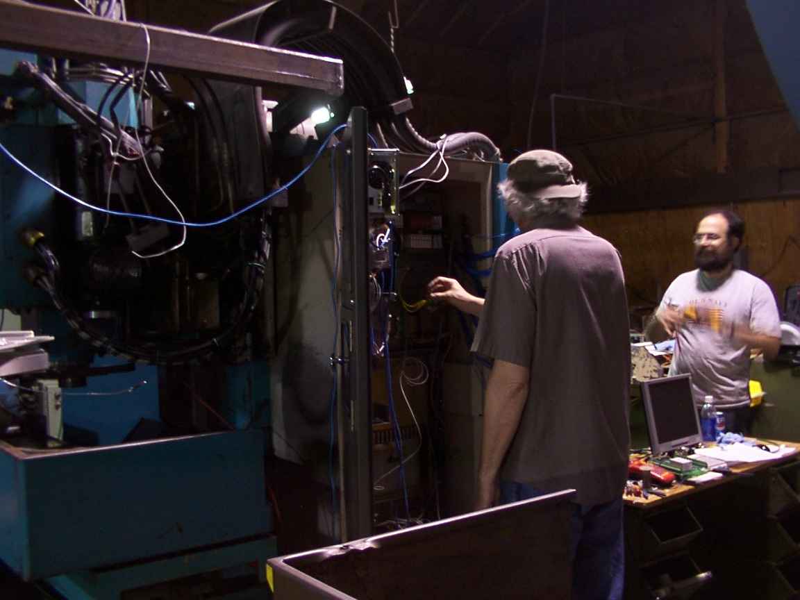
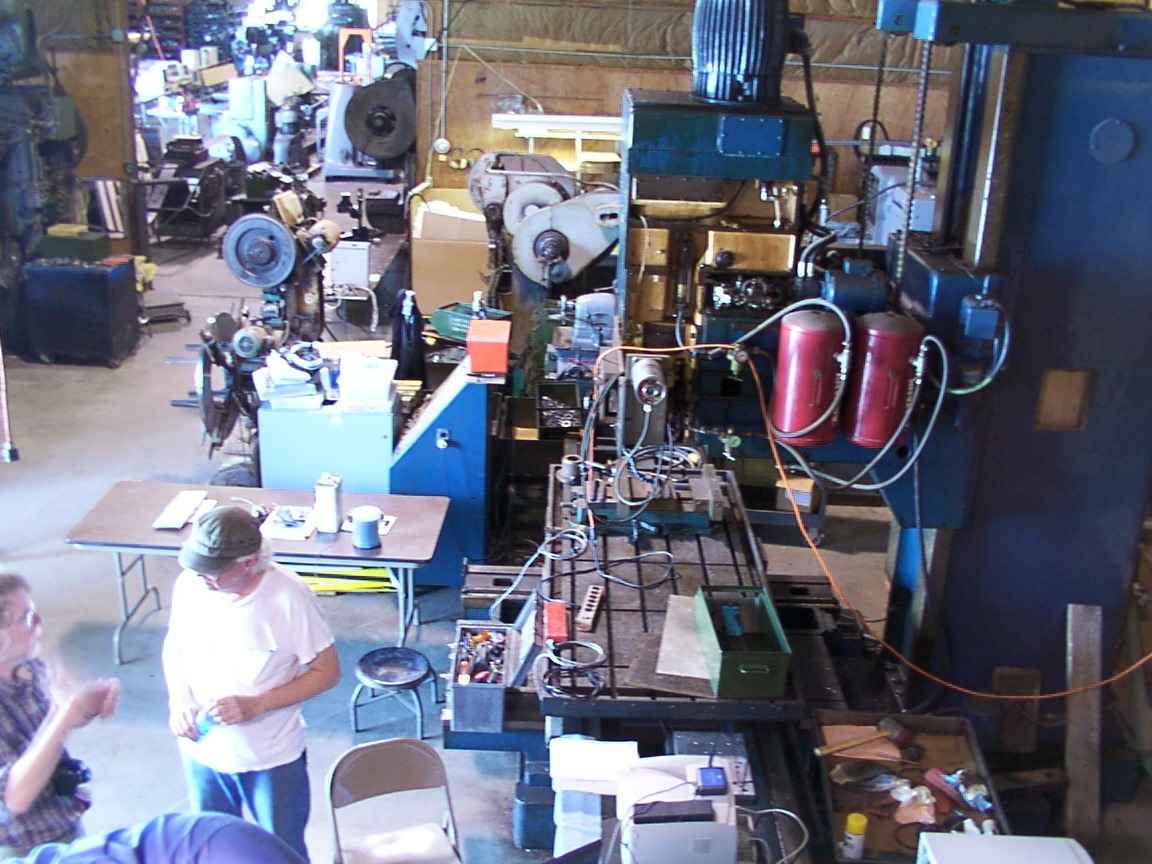
Dave fiddles with the Vital Systems board in the electronics cabinet while John writes a test script for its HAL component. On the cabinet door you can see the computer with its flashy blue glowing power supply. The rainbow cable goes to a rack of 72 opto22 i/o modules. The modules convert between TTL signals and 24V signals with relatively high current. Each module an LED to show what state it is in, and is easily inserted or removed from the rack.
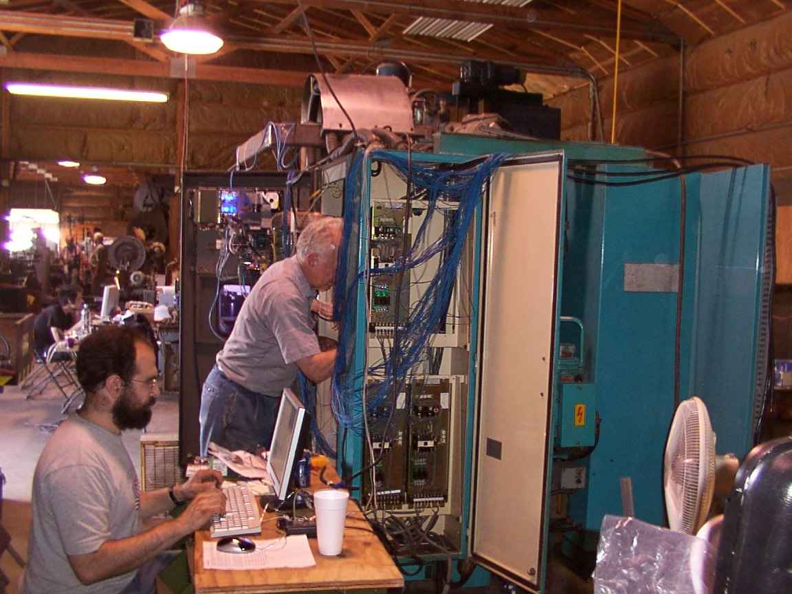
Background: Fenn (Ben Lipkowitz). Foreground: John, Dave. The blue mess of wires goes to the other cabinet. The three gold-ish plates directly behind the blue wiring are the servo amplifiers. The boards swing down for easy access. The black box with eight wires going to it is the infamous sticky servo power contactor.
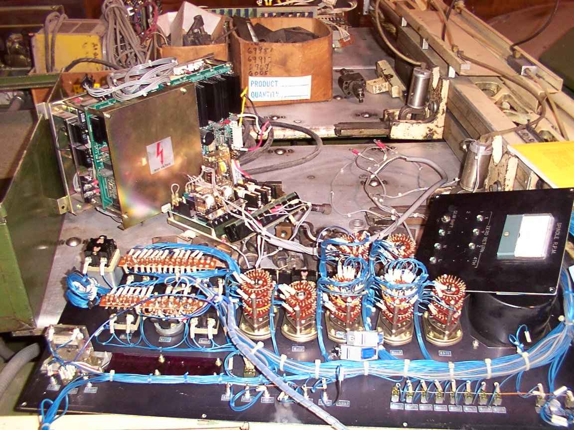
Foreground: Backside of the original front panel. Background: The original 24V power supply? The junk is sitting on top of a CNC punch press. Somewhere around here there is the original 2'x3' motherboard with six 14"x24" extension boards on it.
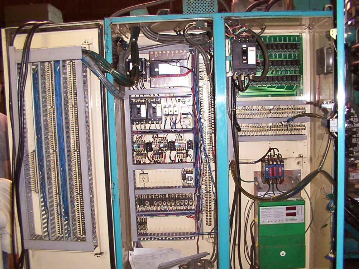
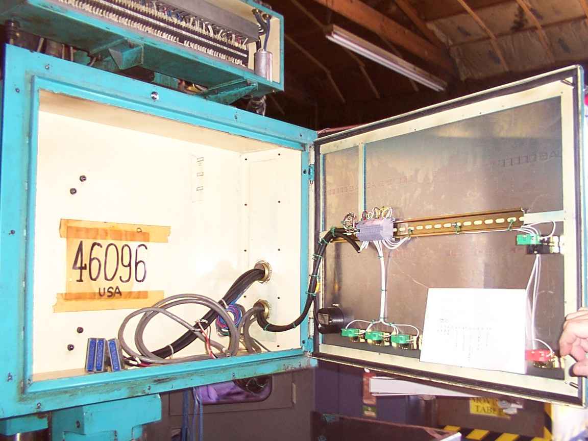
The electrical cabinet. On the top left is the 24V transformer and directly beneath it are the 24V and 110V breakers. Top middle is the main 240V breaker, and directly behind it is the Solid State Relay board, which controls the toolchanger hydraulics and various other electrical devices on the machine, such as ballscrew brakes. The big green box on the lower right is the spindle motor controller.
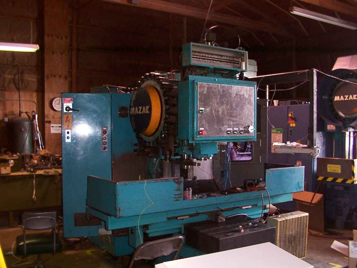
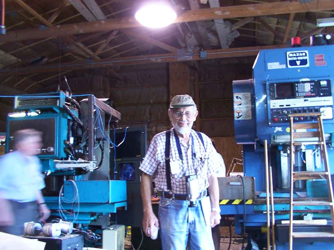
Foreground: our Mazak. Background: the other Mazak.
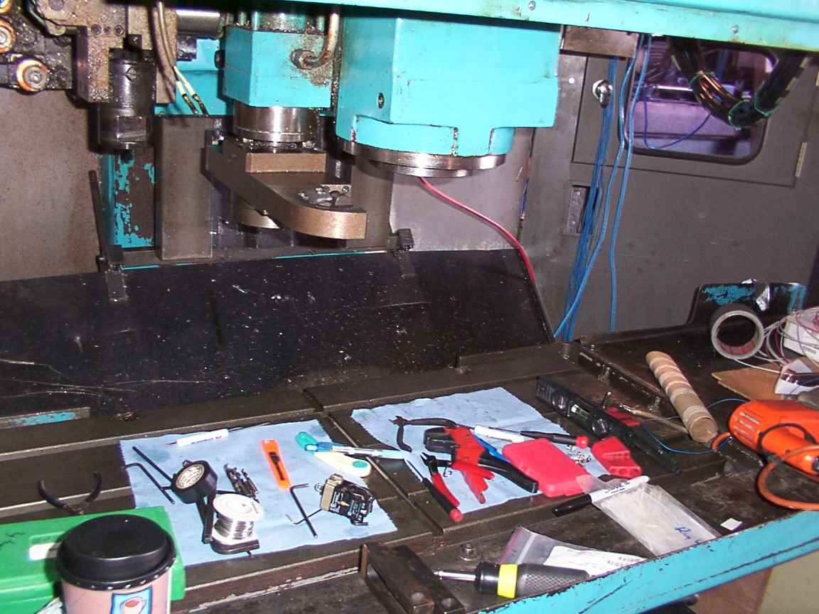
Closeup of (top) the toolchanger shift arm, toolchanger dual arm, spindle, and (bottom) table. The black cylinder on the top left is a toolholder carrier. It is being gripped in the "shift arm" which carries the toolholder from the tool carousel to the "dual arm". The dual arm extends, rotates sixty degrees counterclockwise and retracts to receive the new carrier from the shift arm, which contains the new toolholder, and simultaneously catches the old toolholder in the old carrier as it drops out of the spindle. The dual arm then extends, rotates 180 degrees, retracts in order to pass the old carrier and toolholder to the shift arm to be put away, and simultaneously loads a new tool in the spindle socket. The dual arm then extends, rotates 60 degrees clockwise to clear the spindle, and retracts to clear the work space.
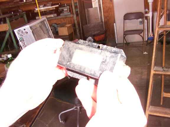
Rear view of the new front panel.
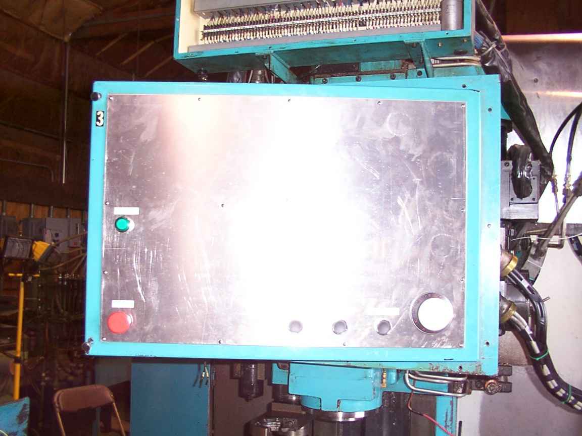
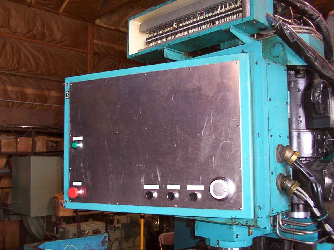
Front view of the new front panel. The labels actually do have writing on them, trust me. Green button turns on the PC, red button is E-Stop, tool release, feed hold, cycle stary, jog wheel. These buttons are for functions necessary while actually doing stuff under the machine, and can be easily located by feeling around the edges of the panel.
Another view of the panel.
Tom Powderly cleaning the grease from his hands.

Matt Shaver and John Kasunich having a committee session.
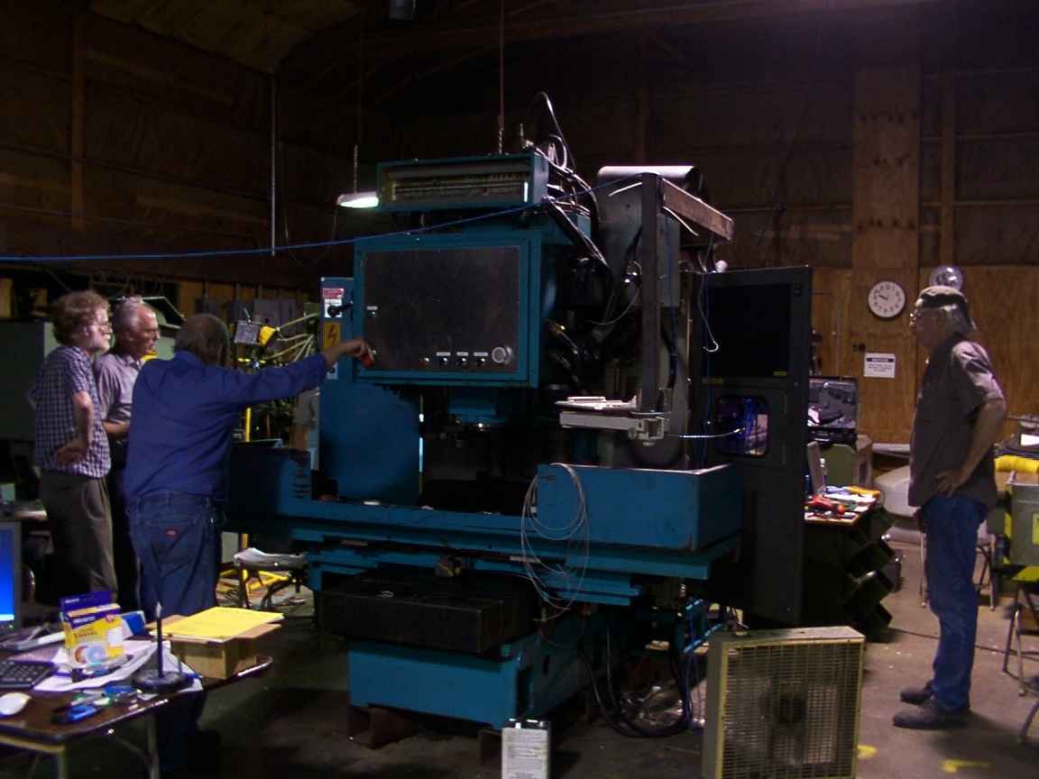
Testing the servo enable circuit for the first time. Jon Elson, Dave Engvall, Ray Henry releasing the E-stop, and Tom Powderly. This is right after the machine drove nearly off the end of the Y axis when the E-stop circuit didn't work due to sticky power contactors in the servo amps.
Trying to figure out what went wrong.
Testing the servo enable circuit. Tom is holding a switch that turns the X-axis servo amp on.
This picture is for you, Dan Falck. It's roland's 20 foot tall mill.

A better picture. The aluminum plates are for the Z motor mount.
Testing the DAC. Sorry for the crappy picture. I was excited and thought the machine might go wild again.
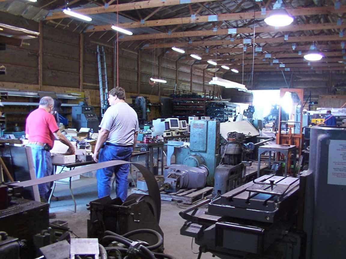
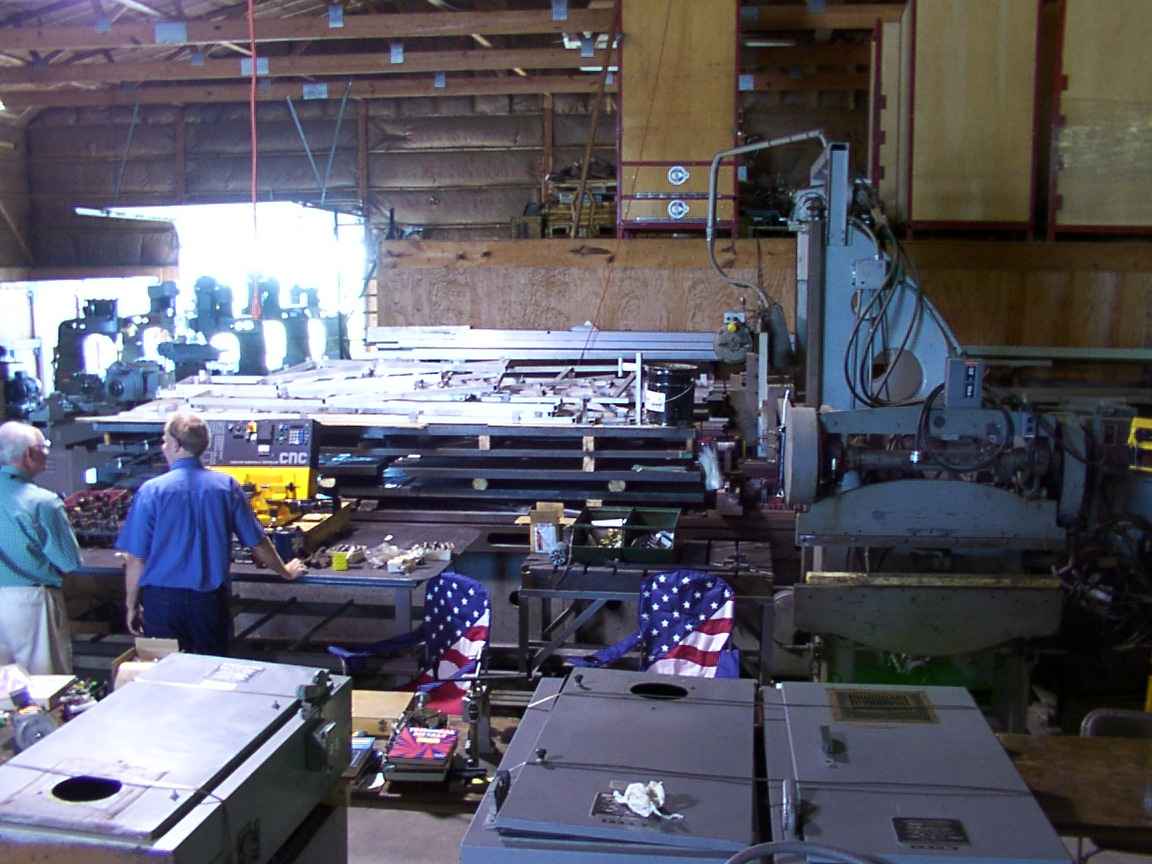
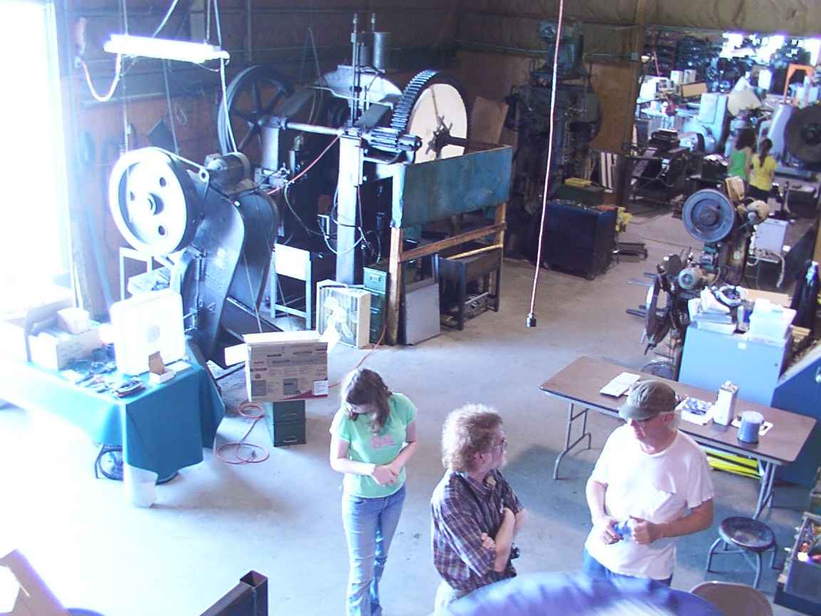
The neighboring room. In the foreground is the roll of sheet stock that goes to the punch press line, and some bridgeport heads/knees. In the near background are the swap meet tables. In the far background are material racks and eight bridgeports being retrofit to CNC. Saturday morning, June 26.
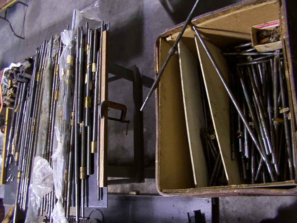
A pile of brand new Acme lead screws from bridgeports and Grizzly mills. The screws were removed to be replaced with ballscrews for a CNC conversion. They were selling for $5 each, bronze nut included, so I bought 15 of them! (for $60!)
Werner Wichia and Frank ?? looking at an Emco compact CNC lathe for sale. In the background is Roland's 20 foot planer. It is actually bigger than it looks!
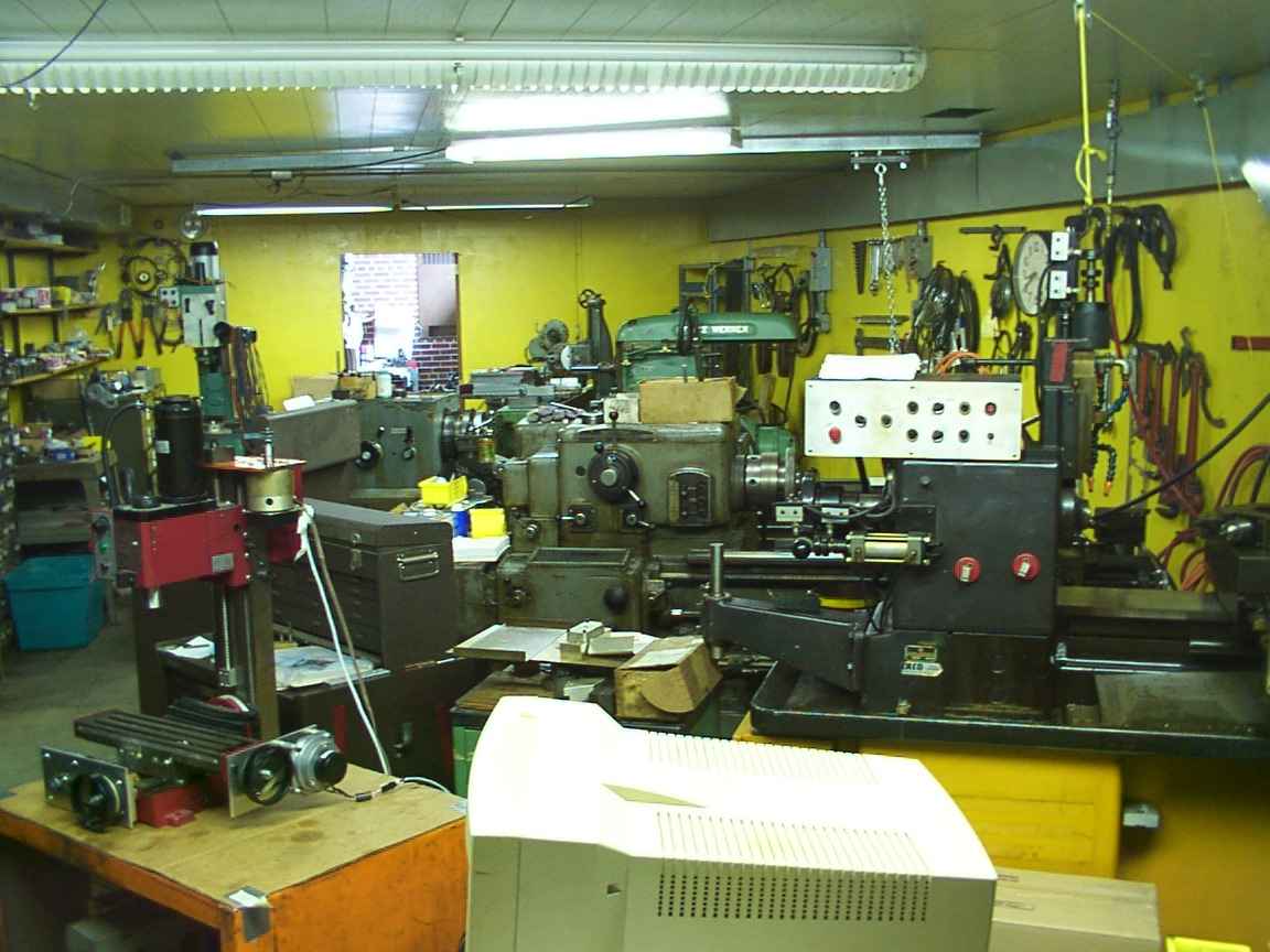
Roland's lathe room. This room feels warm and fuzzy.

Roland's mill room. This room also feels very pleasant to be in. On the left is a manual bridgeport and on the right is a CNC bridgeport. In the background is a rack of fifty or so toolholders and a CNC mill of Roland's own design. Each mill has many clever modifications, such as an arm with a piece of angle iron ont the end that swings in and is clamped in the vise. The knee is then lowered and the vise swings out of the way, with no heavy lifting!

Turned 180 degrees from the previous picture. Notice all the toolholders ready to go!
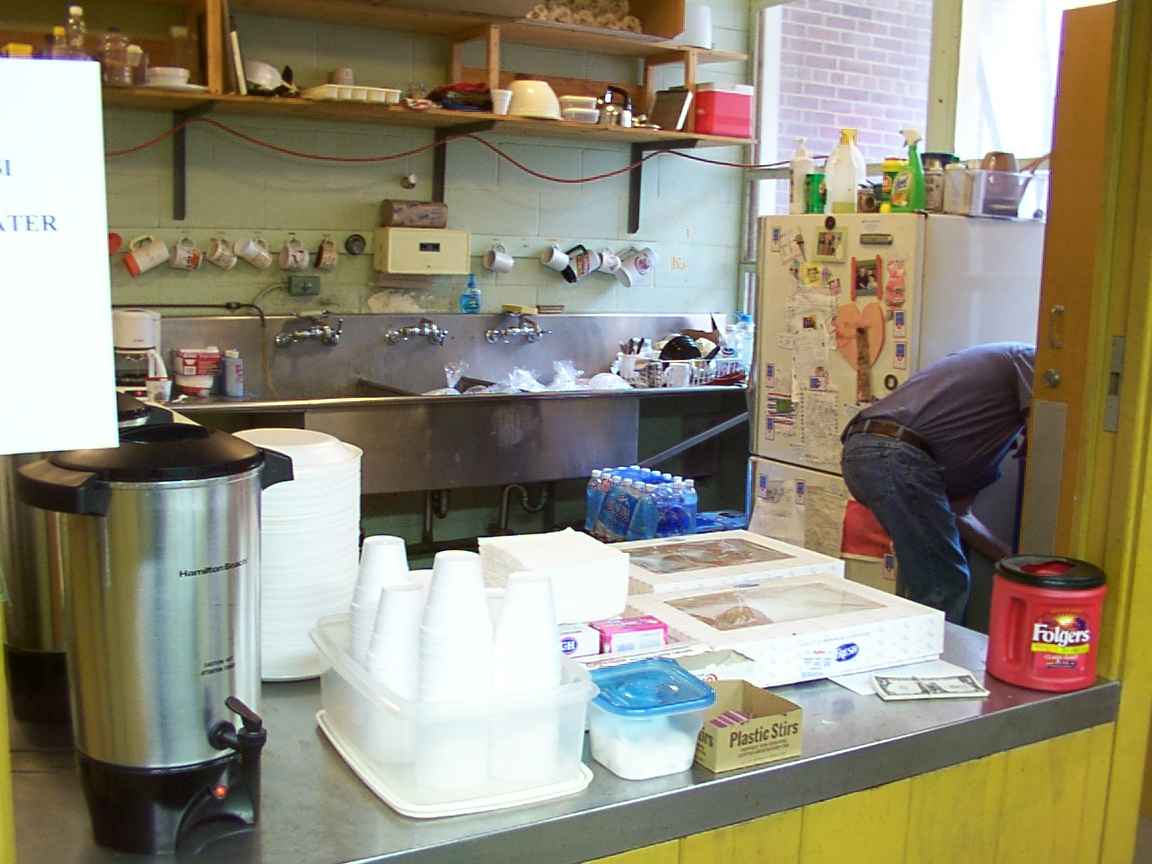
The kitchen, with this morning's donuts and coffee. Today three dollar bills were on sale for one dollar. Joe is adding more (complimentary) drinks to the cooler.
Foreground: someone's CNC punch press and Rick's Rick-O-Matic engraving machine. Background: Rick Chownyk (left) shows off his boxes of stuff.
Rick Chownyk and the Rick-O-Matic. That's a vacuum chuck on the machine's table.

Boris, the cuddly cat.
Bill Volna, expert in kinematic design.
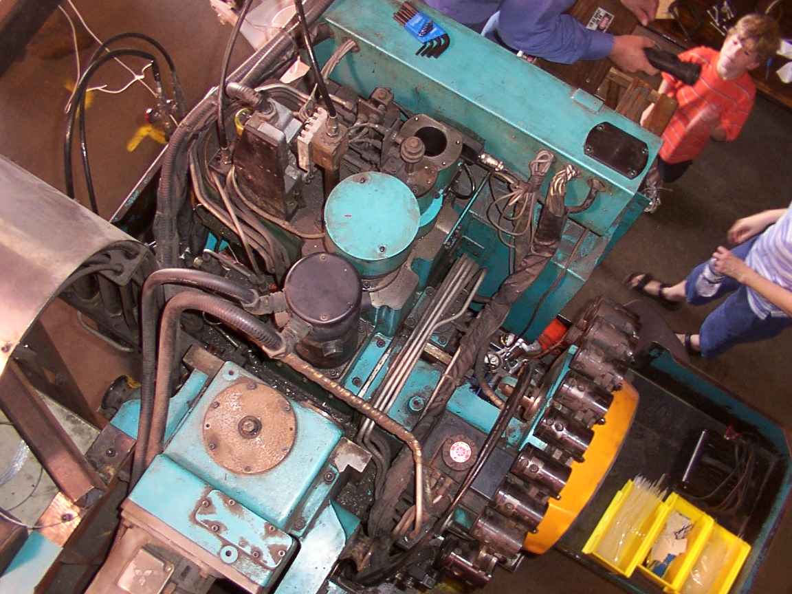
View from the top of the Mazak. Background:Ray Henry's hand, Jon Elson's son, Jon's feet. Starting at the top left, the two black hoses are flood and mist coolant; the gray box with the cable going into it is the Z axis quad roller switch; the heatsink-like object to its right is a slotted table where the switch cams are bolted; to its right is the tool release hydraulic cylinder proximity switches and the cylinder itself, which we will remove later to get at the spindle orient sensor. Directly below it is the Z axis brake and bearing mount (teal cylinder); next is the black Z axis motor, and the plate with six bolts is the column (knee) elevation screw bearing. Finally, on the right is the tool carousel. Sunday morning, June 27.
Another picture of the big mill. Tom Powderly and Jon Elson are on the left. The four-jaw-like shiny disc is actually a reel for holding steel ribbon stock for punching. Behind it is a small punch press.
One of Jon's daughters, Jon Elson, and Tom Powderly. On the left is a press, and behind it is a rather large geared press brake and a medium sized punch press. The presses are all aligned so that stock can be fed through all three automatically.
The spindle orient sensor. It appears to be simply a magnet bolted to the side o the spindle and a coil to detect the changing magnetic field. The black cylinder with the wire coming out of it is the coil.
Another picture of the sensor coil, no flash.
Another picture of the sensor. The green bar is the magnet. It is clamped to the spindle with a green piece of sheetmetal. Odd.
With the spindle turned 60 degrees to the right.
On the opposite side of the spindle there is a small steel plate bolted on, possibly for balance.
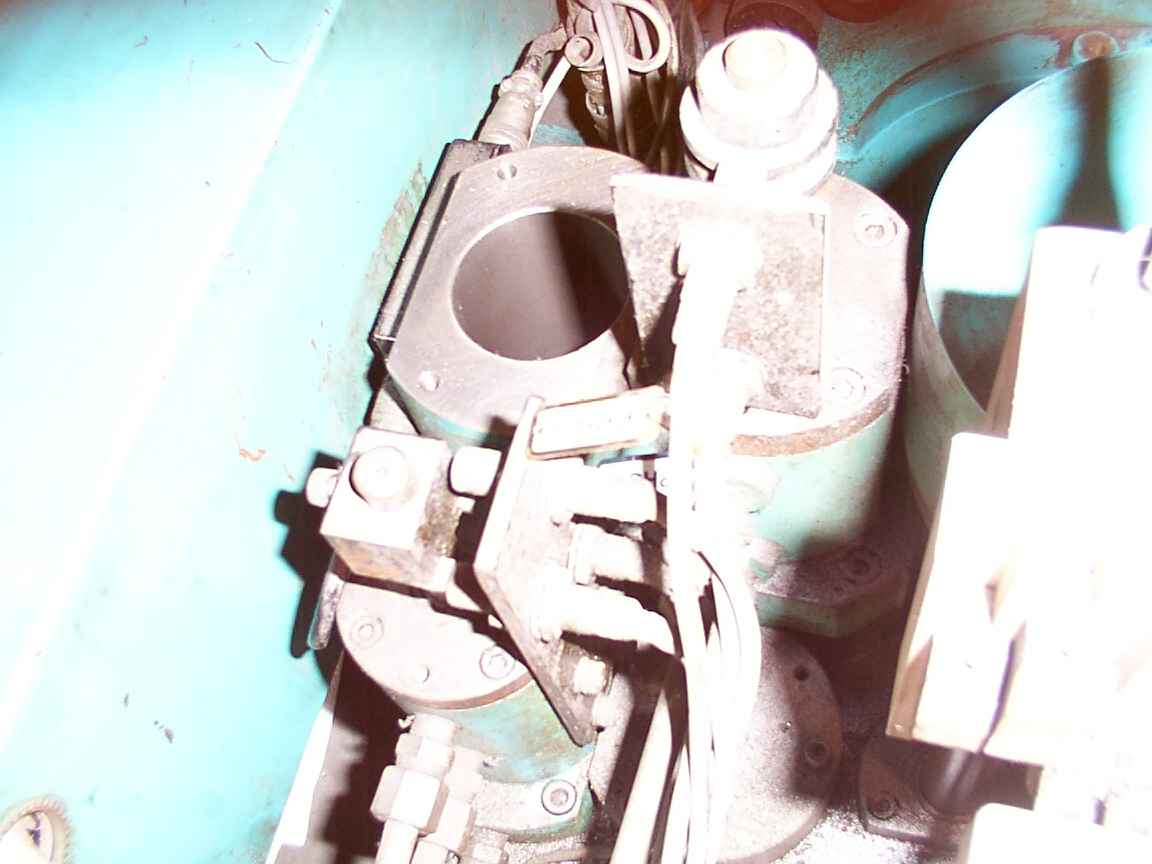
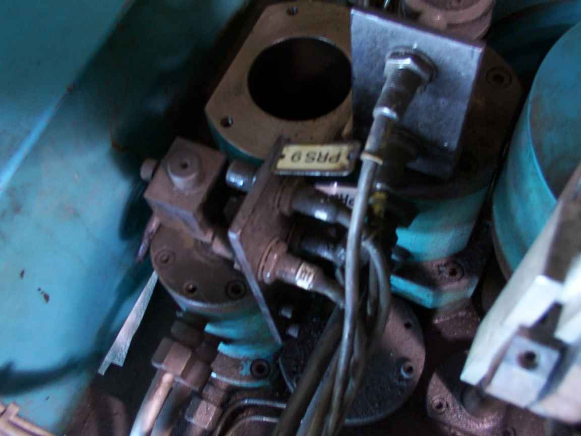
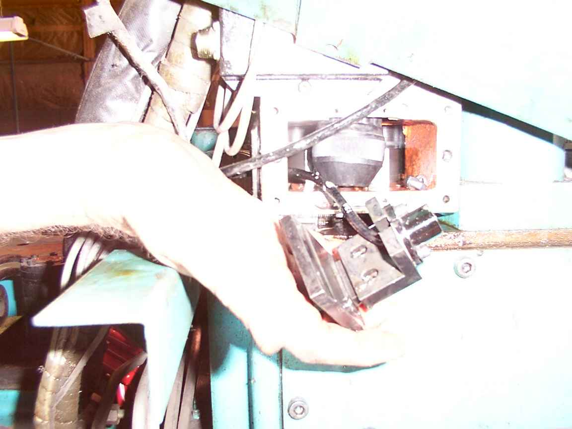
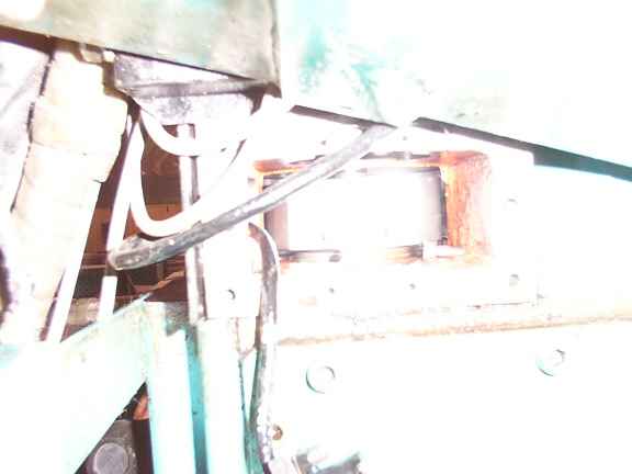
On the left is the gear change cylinder? with its proximity switches. Top left is the hole we were looking down, and bolted to the back of that housing is the magnetic sensor signal conditioner, possibly an amplifier/signal conditioner of some sort. Top middle is the tool release cylinder and its proximity switches, which is directly above the spindle. To the right of that is the Z axis ballscrew brake.
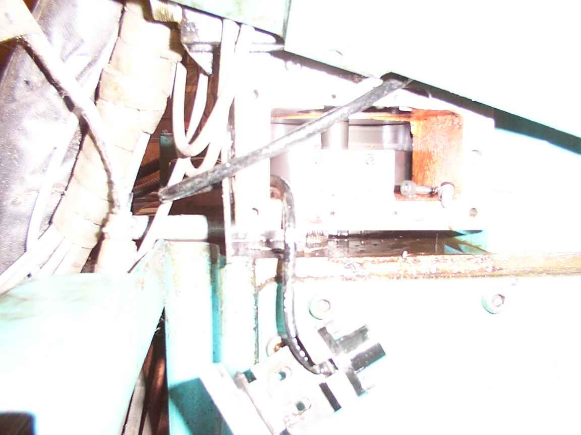
Same picture, no flash.
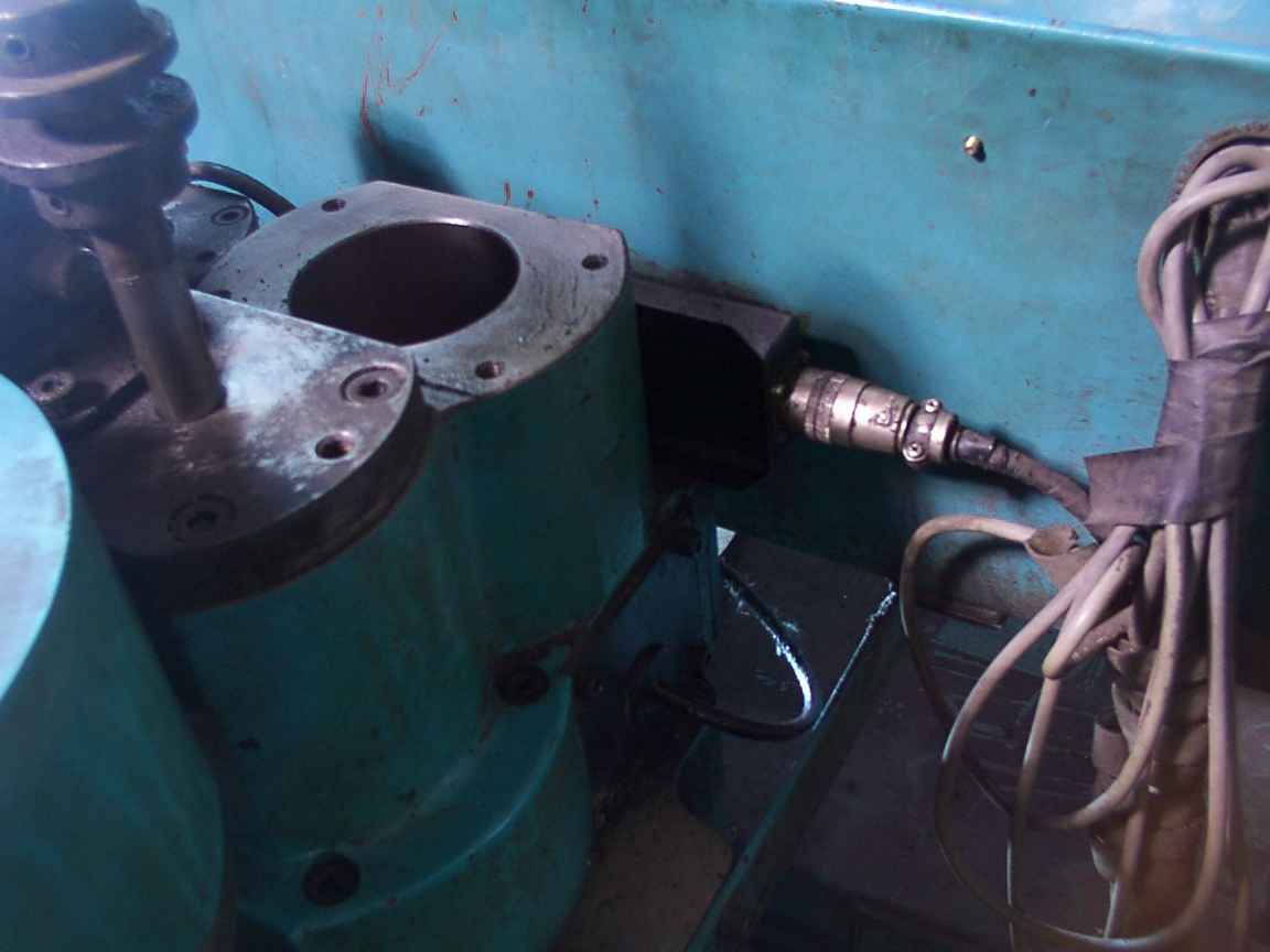
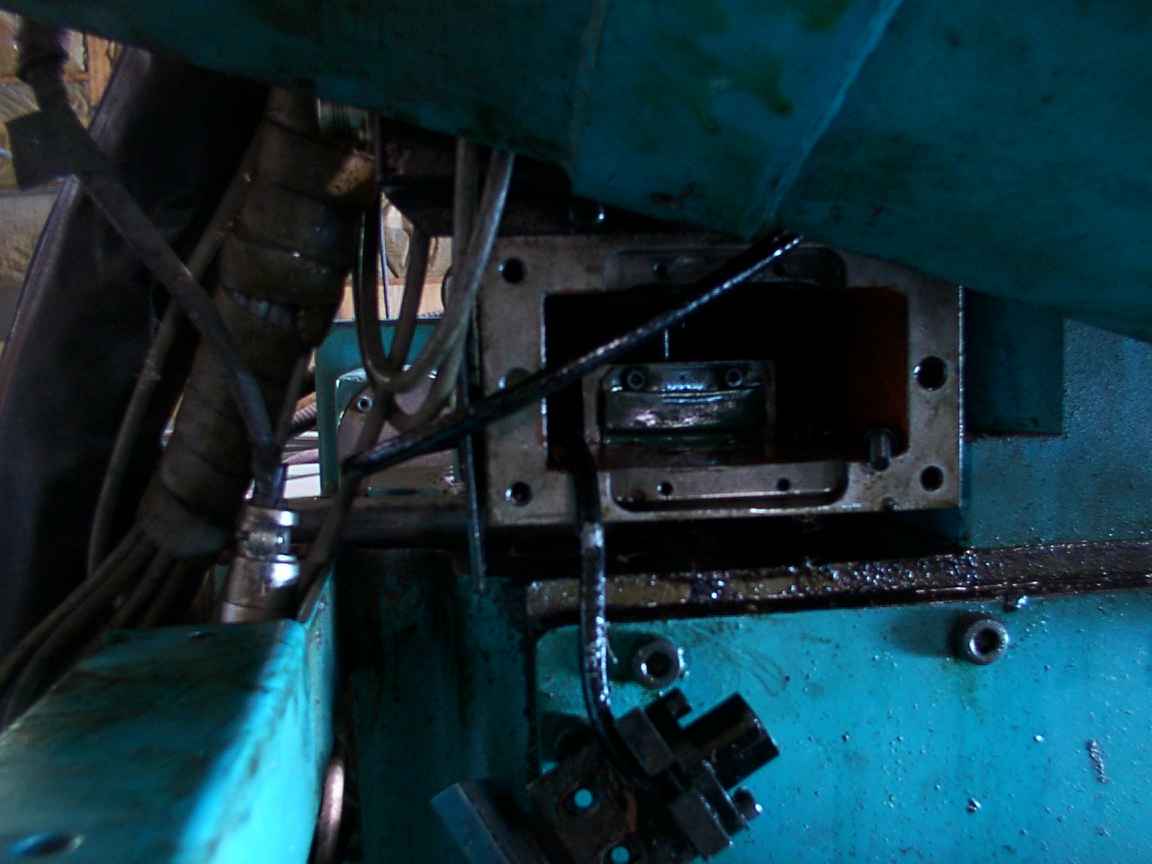
From the other side. The silver electrical connector goes to the magnetic spindle orient sensor.
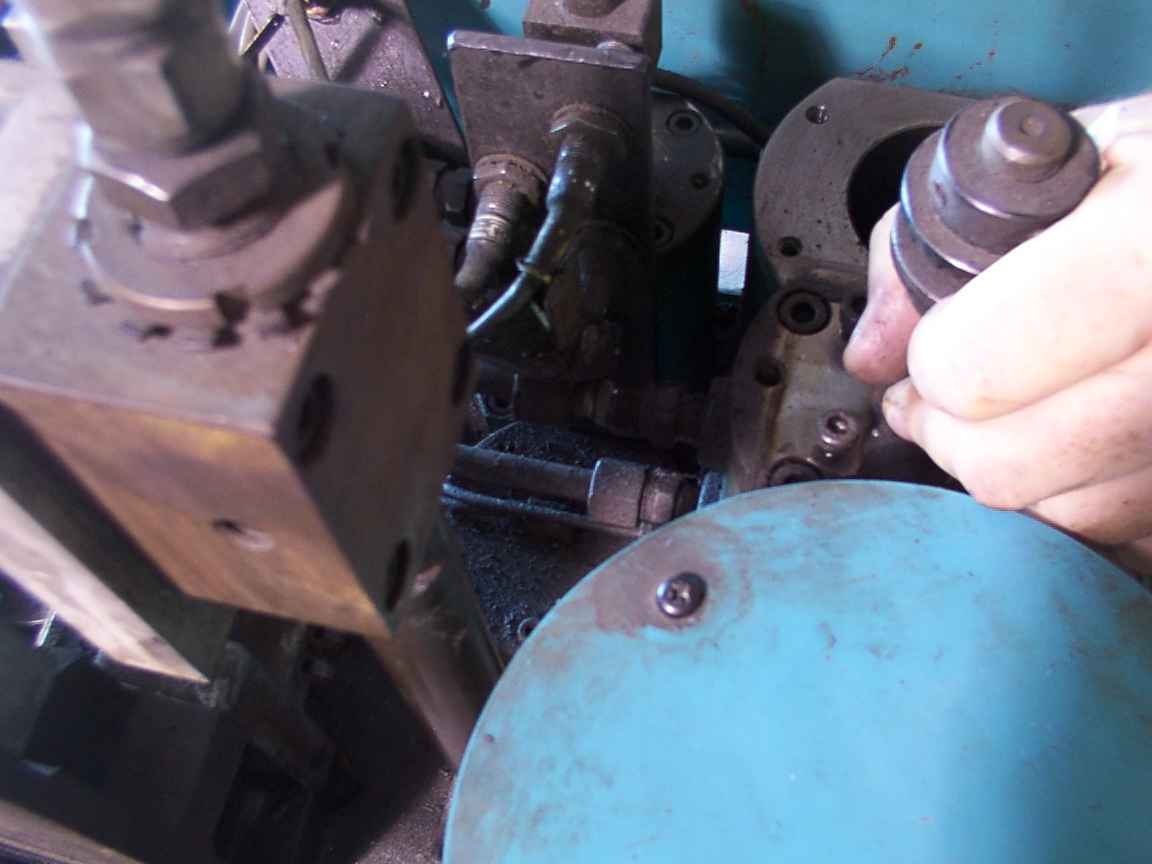
We've removed the proximity switches and unbolted the cylinder. Tom is lifting the cylinder housing. It is stuck on something. At this point I accidentally sprayed hydraulic oil all over the shop by pushing down on the tool release cylinder shaft. You have to turn the shaft to get it to move freely up and down. Use a cup and pump the cylinder up and down to collect hydraulic oil, otherwise it will spill all over the machine.

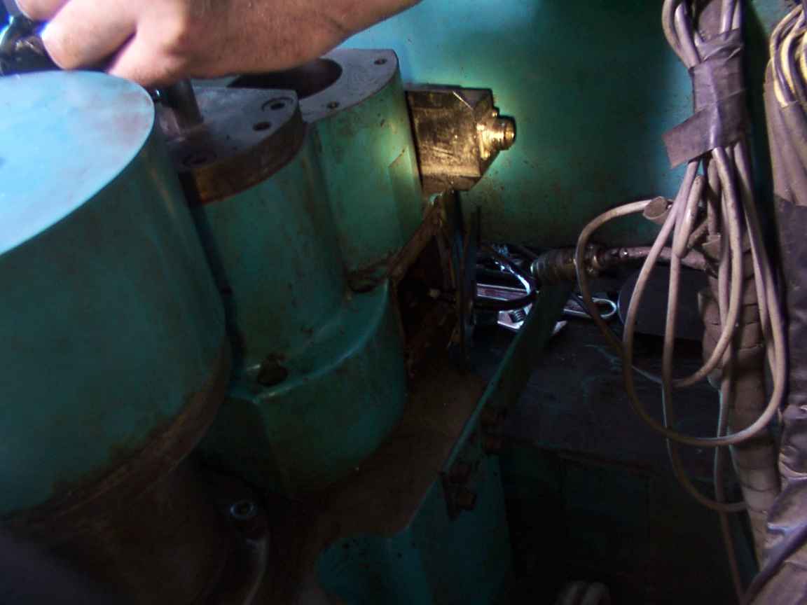
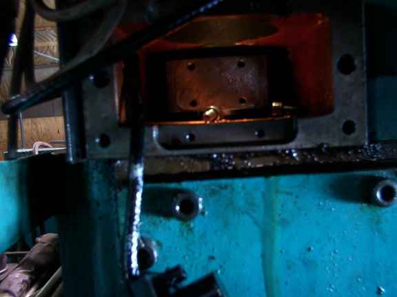
We open the side access plate to look inside.
Don't forget to disconnect the sensor!
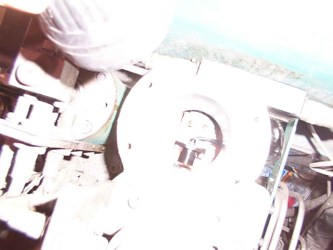
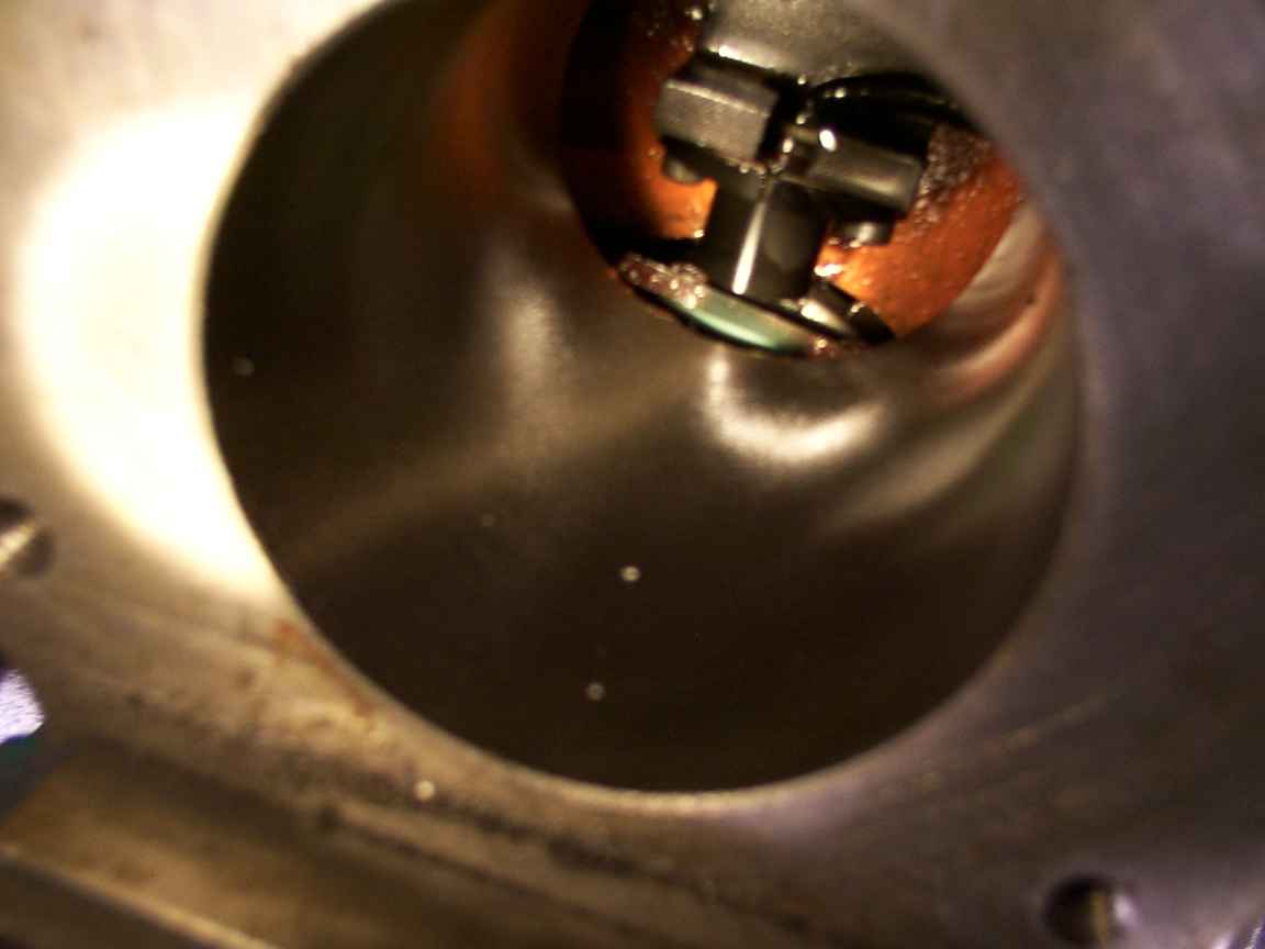
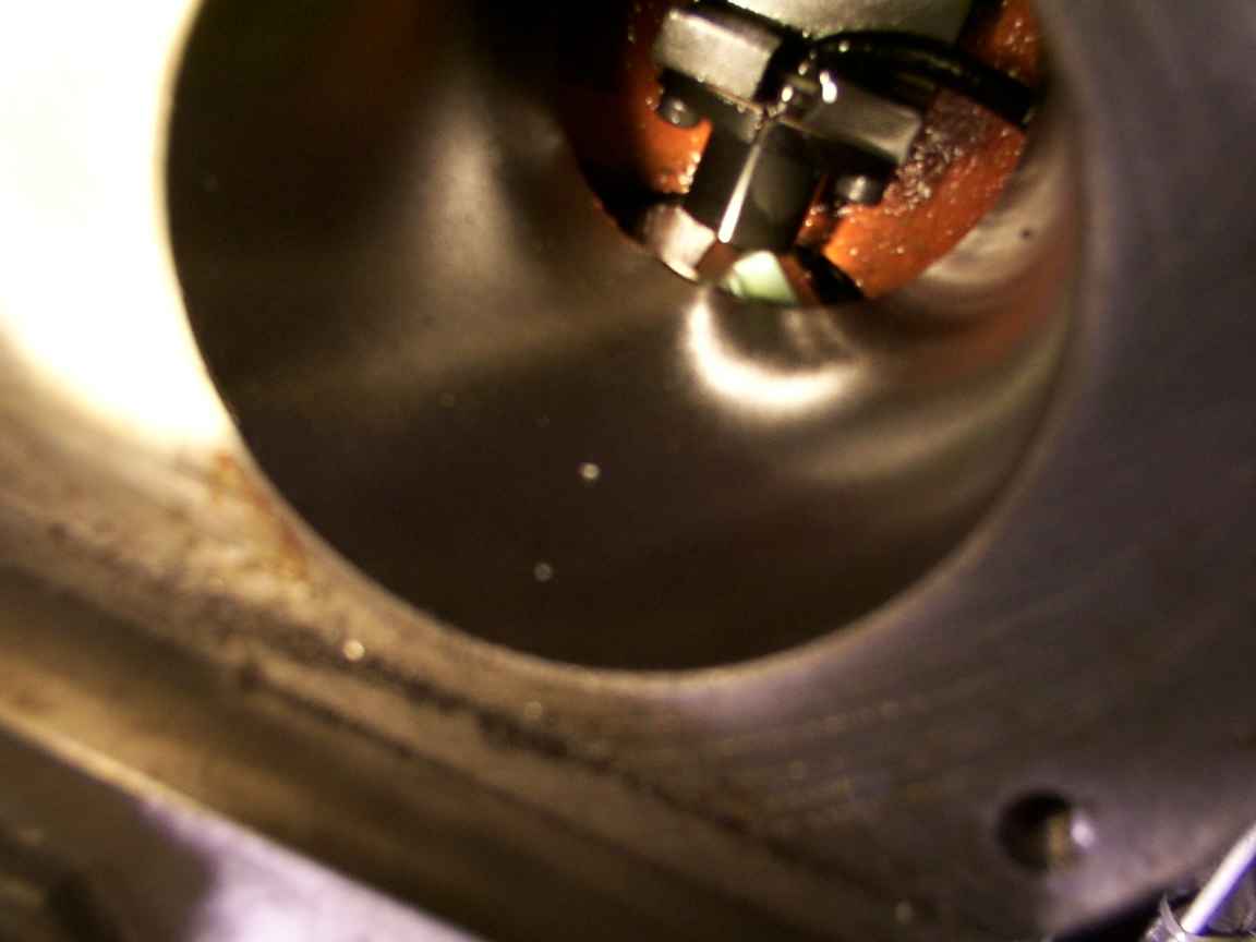
We discovered a front access plate. It's much easier to remove the magnetic sensor through this opening. Shown in front is the sensor coil. (The black chamfered thing inside the cylinder housing is a flashlight.)
Looking back into the cylinder housing. The magnet is held onto the spindle flange with four bolts. Don't forget your extra-long magnetic metric T-handle hex keys! Don't let the lock washers behind these bolts fall down into the spindle bearings.
Same picture.

Ah. Finally found a lighting setup that works.

On the left are the Z axis limit switches. In the middle is the Z axis brake, and to its right is the Z axis motor.
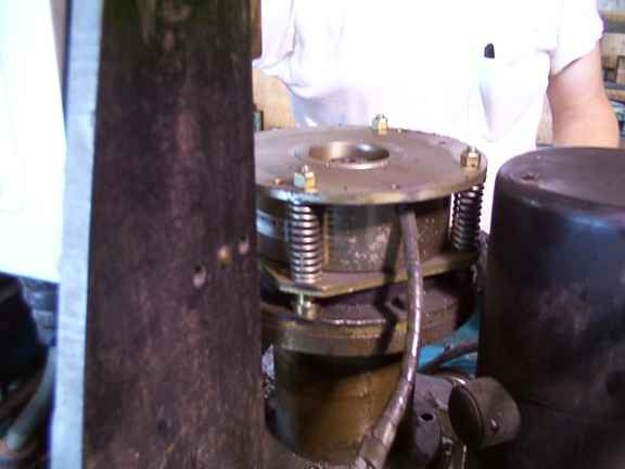
The cover is removed from the Z axis brake. When it is energized, the entire top assembly pinches together, pressing against the brake surface. The bearing mount interferes with the removal of the tool release cylinder, and the brake must be removed before the bearing mount can be removed.
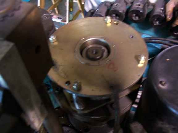
The brake is held on by four bolts and a snap ring.

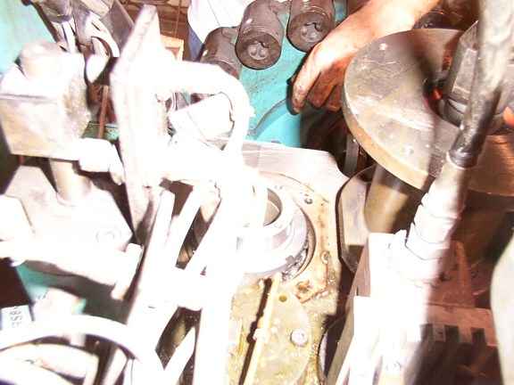
The brake mates with the square flats on the ballscrew end. Here, the ballscrew bearing is shown unbolted, and raised up half inch or so. It doesn't need to be removed all the way to take off the tool release cylinder. Don't forget to put blocks under the spindle so that it doesn't fall down! The ballscrew is very efficient and will spin very fast. You won't be able to stop it with your oily hands. How do you think we know this?
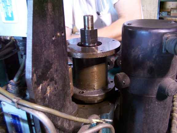
Another picture of the ballscrew bearing. Just enough clearance to remove the tool release cylinder.
Success! Tom hoists out the cylinder housing. It weighs about 30 pounds.

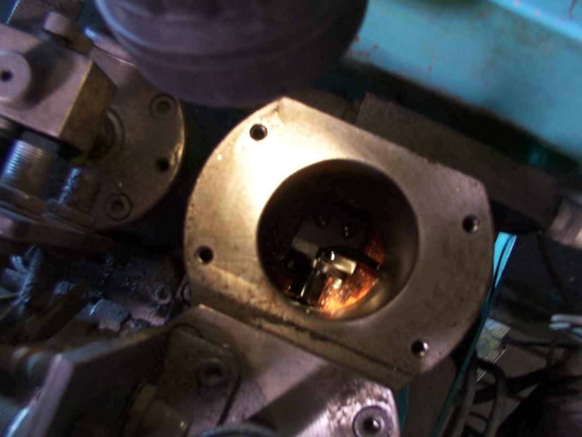
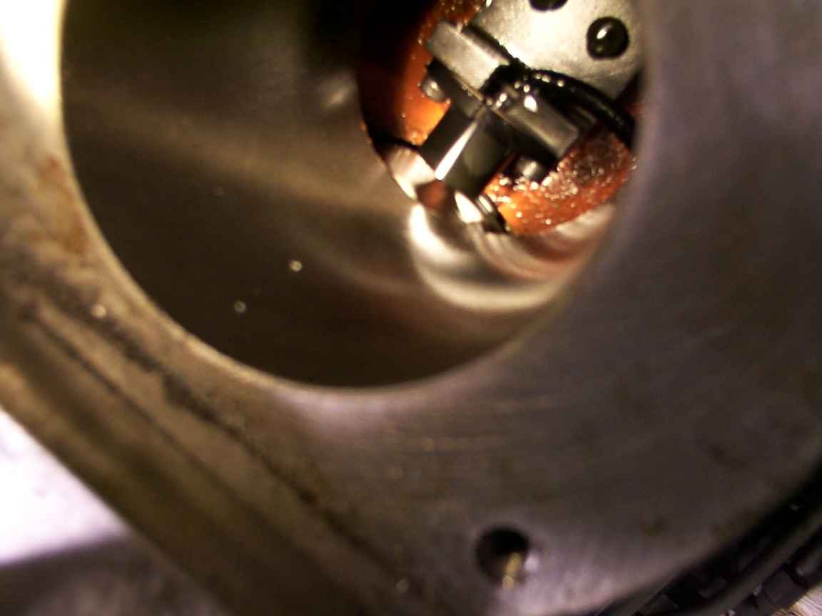
Now, back at the spindle, you can see the flange that the magnet was bolted to. We are removing the four allen screws that secure it to the top of the spindle.
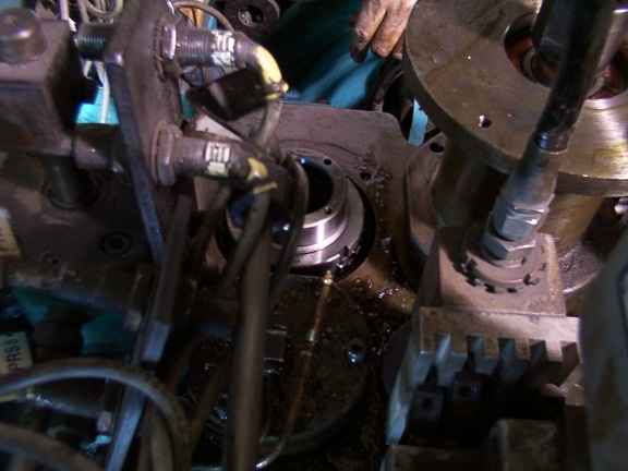
The top of the spindle. The ring with a slot in it is the preload adjustment locknut.
Another picture of the spindle. You can see the preload lock washer (black toothed ring) and the spindle ball bearings directly beneath it.

The bottom of the tool release cylinder. The long shaft pushes down on the top of the spring loaded drawbar.
The magnetic sensor signal conditioner.
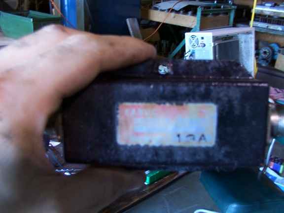
Same picture, no flash. Fanuc. Made in Macon, GA 13A. Whatever that means.
Some time in September(?) we hope to complete the retrofit project and also install a high resolution encoder on the spindle. The magnetic sensor was not accurate enough to allow the dog on the end of the spindle to engage reliably with the toolholder. (gee I wonder why!) A high resolution encoder with index pulse will enable us to orient the spindle for toolchanging, as well as do cool things like rigid tapping. The encoder will only be used at slow speeds. For normal milling operations we will use velocity feedback to control the spindle.